A hydraulic pump schematic symbol shows energy conversion and functional options, not the pump's physical shape. Arrows, control lines and drain connections help identify the pump type and circuit role.
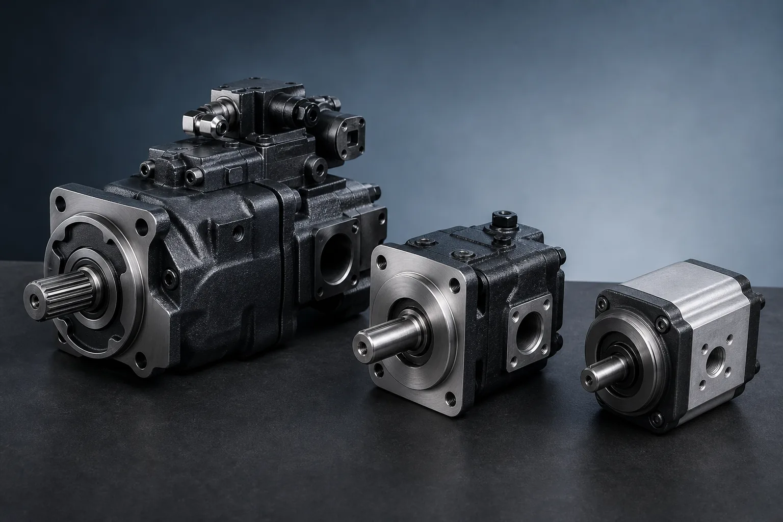
Identify a hydraulic pump from its circuit and nameplate.: Send the schematic, pump tag, complete code, nameplate, machine function and photos for replacement review.
Common pump symbol features
- A circle with an outward triangle identifies hydraulic pump flow
- A diagonal arrow across the symbol indicates variable displacement
- Two opposed flow directions can indicate reversible operation
- Dashed control lines show pilot, pressure-compensator or load-sense signals
- A separate case-drain line must return with acceptable backpressure
Open- and closed-circuit context
- Open circuits normally draw from and return fluid to the reservoir
- Closed loops connect the main pump ports directly to motor ports
- Closed loops require charge, make-up, relief and often flushing functions
- Pressure-compensated pumps destroke when the control pressure is reached
- Load-sense controls maintain a pressure margin above the highest load signal
Using a schematic for pump sourcing
- Pair the circuit symbol with the complete pump nameplate and model code
- Identify displacement, control, rotation and required pressure
- Trace case drain, load-sense, pilot and through-drive connections
- Confirm shaft, flange and port information from drawings or the installed unit
- Record unresolved circuit functions as open points before quotation