Pump sizing starts with the work the system must perform. Flow determines actuator speed, pressure follows the load and input power must include real system efficiency.
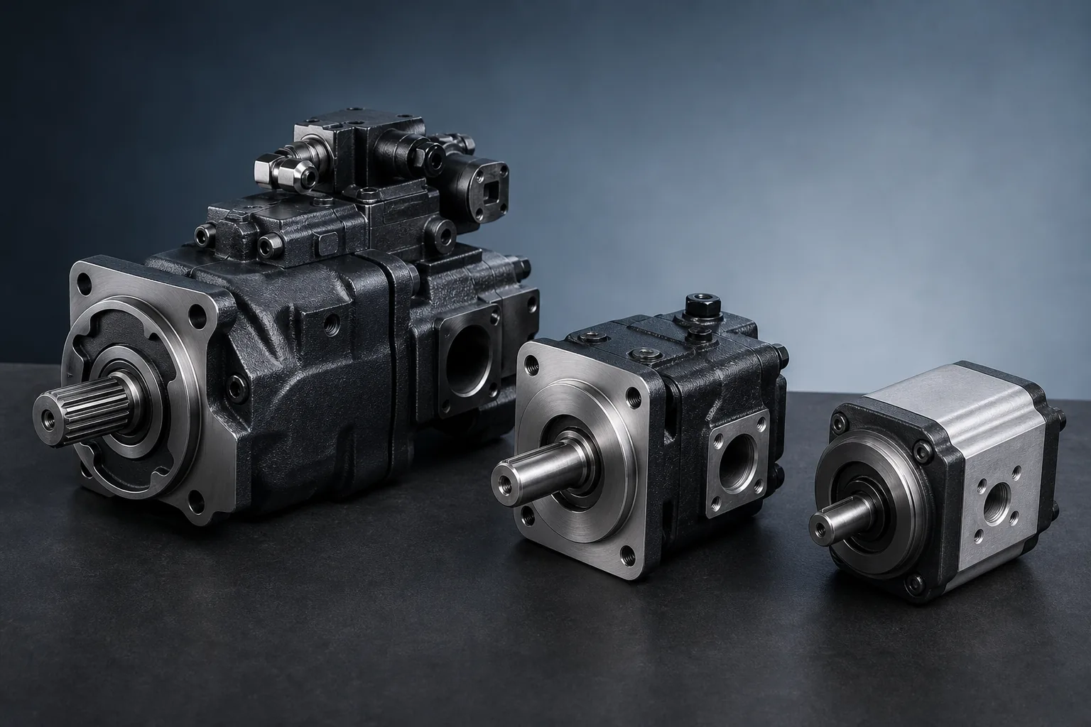
Send the original reference: Include the complete model code, quantity, destination and available photos or drawings.
Core sizing formulas
| Question | Metric formula | Use |
|---|---|---|
| Pump flow from displacement | Q (L/min) = displacement (cc/rev) × speed (rpm) × volumetric efficiency ÷ 1000 | Estimate delivered flow |
| Cylinder extension speed | v (m/s) = Q (L/min) ÷ [6 × piston area (cm²)] | Check cycle speed |
| Hydraulic output power | Pₕ (kW) = pressure (bar) × flow (L/min) ÷ 600 | Ideal hydraulic power |
| Estimated shaft input | Pᵢ (kW) = Pₕ ÷ overall efficiency | Size the driver with losses included |
Use manufacturer performance data when available. A formula estimate does not replace the speed, pressure and control limits of the selected pump.
Worked pump-flow example
A 45 cc/rev pump running at 1,450 rpm with estimated volumetric efficiency of 0.90 delivers approximately 58.7 L/min: 45 × 1,450 × 0.90 ÷ 1,000.
Worked power example
At 210 bar and 58.7 L/min, ideal hydraulic power is about 20.5 kW. At 85% overall efficiency, estimated shaft input is about 24.2 kW before considering starting conditions and the motor service factor.
What the simple calculation does not capture
- Pump control and standby behavior
- Pressure losses through valves, filters and piping
- Fluid viscosity at startup and operating temperature
- Intermittent peak pressure versus continuous duty
- Prime-mover torque curve and acceleration
- Cooling capacity and heat rejection
Replacement sizing checklist
- Do not increase displacement without checking driver power and circuit flow limits
- Do not reduce displacement without checking required actuator speed
- Confirm maximum and minimum pump speed
- Check continuous and peak pressure separately
- Match open- or closed-circuit design and the complete control code
- Verify shaft, flange, rotation and ports after hydraulic sizing
Information to put on the RFQ
- Required flow or actuator cycle time
- Working and peak pressure
- Drive speed and available motor power
- Fluid and temperature range
- Duty cycle and machine application
- Original model code and installation drawings