Rotation, flange and shaft errors can prevent installation or damage a pump. Use the manufacturer view convention and dimensional evidence rather than hose position alone.
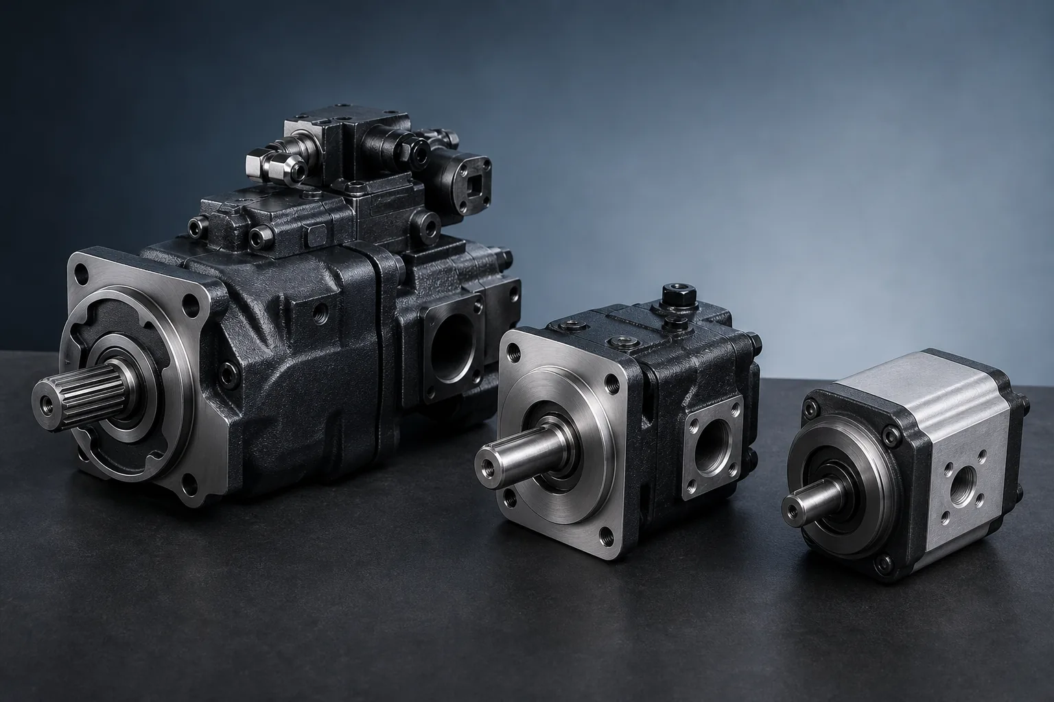
Send the original reference: Include the complete model code, quantity, destination and available photos or drawings.
Rotation
- Record the direction stated in the complete model code
- Confirm the manufacturer viewing convention
- Photograph the drive-end and port side
- Do not infer rotation only from inlet and outlet position
Flange and shaft
| Item | Record | Common error |
|---|---|---|
| Mounting flange | Pilot diameter, bolt pattern and flange standard | Calling all two-bolt flanges identical |
| Shaft | Spline or keyed type, diameter, tooth count and length | Measuring only the worn exposed section |
| Port layout | Port size, thread, position and direction | Assuming hoses can always be rerouted |
| Through drive | Interface and supported auxiliary pump | Ignoring an attached rear pump |
Useful RFQ photos
- Full nameplate
- Drive-end shaft and flange
- Port-side view
- Control or compensator
- Overall installed pump and coupling
Common mounting families
Most pump mounting flanges belong to established two-bolt or four-bolt families. The family name is only a starting point; the pilot diameter, bolt circle, bolt size and shaft extension decide whether a unit actually fits.
| Mounting family | What to record | Risk of guessing |
|---|---|---|
| Two-bolt flange (SAE-style) | Pilot diameter, bolt spacing, shaft type and keyway | Similar-looking two-bolt flanges differ across displacements |
| Four-bolt flange (SAE/ISO-style) | Bolt circle, pilot diameter, bolt size and shaft end | Bolt pattern and pilot are checked separately, not assumed |
| Inline or cartridge mount | Port spacing, housing bore and retention detail | Inline mounting depends on exact housing dimensions |
Verification order before ordering
- Read the complete model code and confirm every suffix
- Compare the flange pilot and bolt circle against the existing unit
- Compare shaft type, diameter, keyway or spline against the coupling
- Confirm rotation direction using the manufacturer view convention
- Check port size, thread, position and through-drive interface
- Keep the nameplate photograph attached to the inquiry record