A pressure reducing valve controls pressure in a downstream branch. Adjustment should be made against the circuit diagram and manufacturer procedure with a verified gauge—not by counting screw turns.
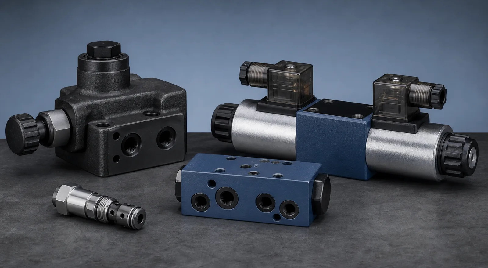
Need a pressure-control valve replacement?: Send the complete valve code, circuit function, setting range, pressure, flow, mounting and destination for a matched quotation.
Before changing the setting
- Confirm the valve is a reducing valve and identify the controlled port
- Review the circuit, valve model, adjustment range and maximum ratings
- Install a calibrated gauge on the downstream branch
- Bring oil temperature and supply pressure into the normal operating range
- Apply the machine lockout and commissioning procedure
Controlled adjustment sequence
- Back off the adjustment only as directed by the valve documentation
- Start at low system demand and observe upstream and downstream gauges
- Increase the setting gradually while monitoring the controlled branch
- Cycle the actuator and verify pressure under both static and flowing conditions
- Lock the adjuster and record the final setting and test conditions
When adjustment does not hold
- Check upstream pressure margin and return-line backpressure
- Inspect pilot or drain routing, contamination and sticking components
- Confirm flow is within the valve range
- Check whether another relief or reducing valve is influencing the branch
- Replace or service the valve only after confirming the complete model code
Settings, symptoms and likely causes
| Observed behaviour | Likely causes | Check before changing the valve |
|---|---|---|
| Downstream pressure rises with demand | Low upstream margin, incorrect drain, or internal leakage | Supply pressure, drain line and pilot connection |
| Downstream pressure drifts over time | Temperature-sensitive viscosity, contamination, or sticking spool | Oil temperature, filter condition and valve cleanliness |
| Pressure cannot be set within range | Wrong valve family, damaged seat, or wrong spring | Complete model code, rating and documented adjustment range |
Record kept after commissioning
- Complete valve model code and serial or order reference
- Final setting, gauge position and oil temperature
- Supply and downstream pressure under static and flowing conditions
- Any circuit changes or differences from the original drawing
- The person and date responsible for the adjustment